Developing a partially foiling canting keel sailing yacht with gennaker - radio controlled
- Hans Genthe
- 30. Jan. 2020
- 15 Min. Lesezeit

In January 2015 stockmaritime started the most unusual and complex model yacht project in the company's history. Shortly after each other 2 customers called, a regular customer, who collected our yachts, asked when we will finally bring out something new and big. I meant only if a customer pays for the development. He replied, "Okay, I'll take part.“ The same day, the Christian-Albrechts-University of Kiel asked if we could build a boat for a research project.
This suddenly meant financing a new model yacht development is finished.
The Chair of Automatic Control of the Faculty of Engineering at CAU Kiel developed a control system to dynamically deform a wing rig. The new and innovative thing about the wing is that the profile can be deformed asymmetrically to starboard and port. In the neutral position the profile is symmetrical. The profile depth and the twist of the wing will be infinitely variable. In laboratory tests piezoelectric contractors are changing the profile.
Thus we manufactured the platform on which the system is to be tested. In addition, we supplied know-how from the sail sector, especially on the subject of aerodynamic design of the wing. The special wafer-thin carbon plates for the wing also came from our production. Thus the M155 became the platform for the EU-funded research project "Smart Maritime Structure Control Lab" of the Christian-Albrechts-University Kiel.
Pushing the edge
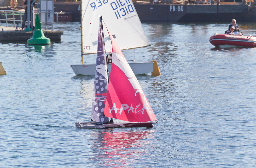
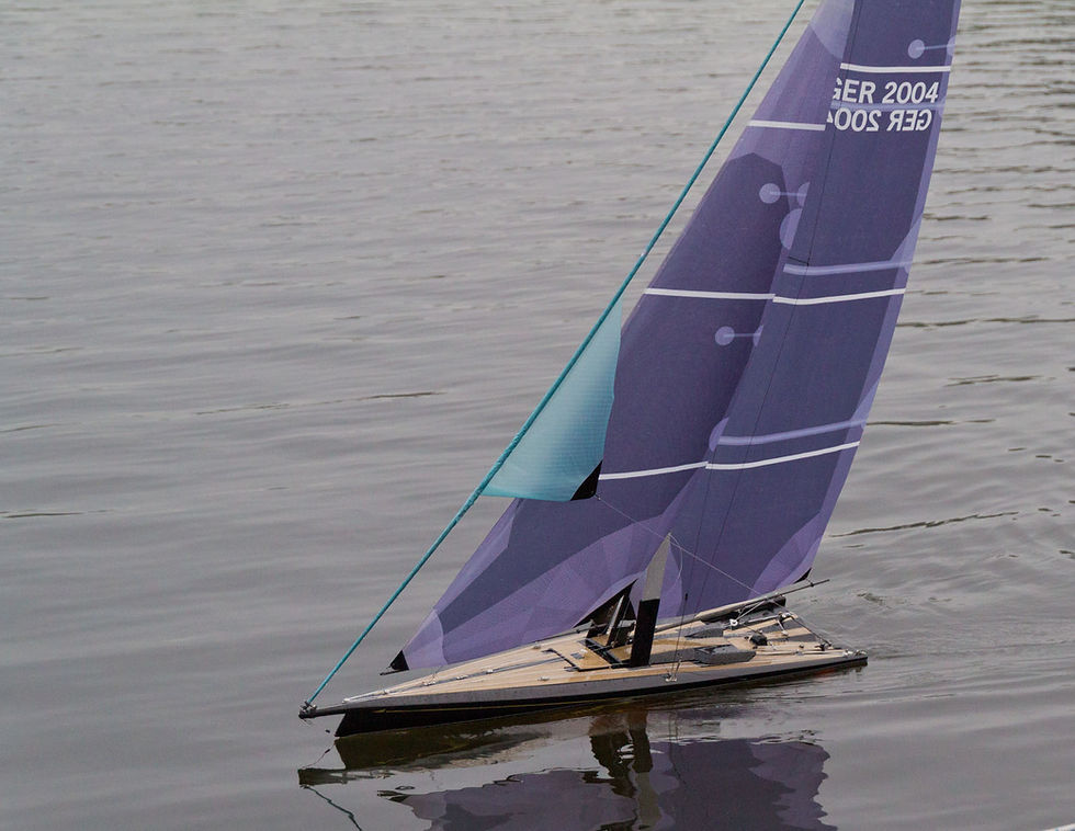
The new boat should also become something very special on the RC market. So we decided to investigate to what extent Canting Kiel and Gennaker can increase the space sheet performance of a model boat, and whether all this is reliable and relatively easy to operate.
The hull construction
One of the basic ideas behind the boat (we've named it MegaMaxi) is to draw a hull that has as little wetted area as possible in light winds, and a wide stern with flat lines in stronger winds. The exit angle of the lines in the stern in relation to the waterline has a considerable influence on the ability of a yacht to break away from its wave system, i.e. to leave the stern wave behind and enter the planning state. The less weight, the flatter the lines become. The planning ability of a yacht is thus in direct proportion to its weight.
This explains relatively simply why an X99 built 85 (2.87t) is still faster than the XP33 (4.3t). 1.7t bomb of the XP 33, however, provides better characteristics upwind, in relation to 1.3t lead in the fin of the X99. Of course there are some other factors to consider, such as crew weight and sail area. As there is mainly little wind on the Baltic Sea, and mostly up- and downs are sailed, the XP is the better choice for these conditions. But this changes if good wind come from behind. The situation is similar, for example, with model sailing with the IOM. The restriction to the UP- & Down-course is type-forming, produces a very special boat shape, which is extremely distinctive in Britpop and Michael Scharmers designs.
Back to the big boats: By the optimal use of the crew, even considerably better characteristics can be achieved, as can be seen on the ASSO99. With only 1.1t total weight and 0.5t lead in the fin. Thanks to 3 men in the trapeze the ASSO has a yardstick of 84, the X99 91, and the XP33 85. All three boats are almost equally long and wide. For the Megamaxi, which is not meant to be an up and down boat, but should be fast over all courses and wind conditions, this means above all: radically saving weight to be able to realize a flat underwater hull. The canting keel allows a considerable weight saving, because the weight of the bomb can be reduced because it´s used more effectively.
At the last Sydney Hobart Race it was exciting to see how the broad Comanche stood up to the slender Wild Oats. In 2014 the Wild Oats was faster in light winds, the better all-rounder. In 2015 and 2016 the Comanche was the first to cross the finish line in heavy winds. 2018 again Wild Oats in light wind.
So how do you design a good all-round boat?

Of all bodies, a circle has the smallest surface area at maximum volume. A circular frame cross-section therefore means minimal friction, but more rocker (curvature of the longitudinal lines). A flat underwater hull means more friction, but less rocker. The MegaMaxi is designed to have a circular frame cross-section at O degrees heel and a flat hull at 22 degrees heel. Here the sketch with the basic idea and the canting keel. 50 degree canting angle and 22 degree heeling means 72 degree deflection. At 22 degrees the dimensional stability increases radically, but also the wetted surface and thus the frictional resistance.
Seawater resistant
Our experience is to avoid the water in the boat is the most important point to achieve reliability. The best solution so far has been a round lid, as it exerts even pressure on the rim. Ideal is the classic Weckeldeckel lid, this famous German brand you can buy everywhere, and it is air- and watertight - tested a million times in the household. So we have subordinated the deck layout not only to the function, but also to the Weckeldeckel sizes.
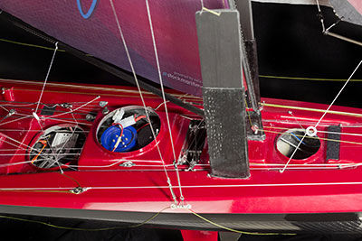
1st cover in front: battery compartment
2. cover in the middle: sail winches for gennaker, furler (jib furler) and canting keel/daggerboards
3rd cover at the back: Receiver, sail servo, rudder servo and overload protection switch
On top of this are covers for optical reasons. Bur the deckhouse in the middle provides splash protection also for the only openings into the interior.

Since on fast ships the splash water comes from the front, this area always remains dry. The water that flows under the covers is led through the recesses in the deck to the rear into the cockpit, the water that penetrates under the 3rd cover is led from there through two 10mm bilge pipes to the transom. By the way, the lines for the daggerboard circulation, the jib furler and the jib sheet run in the long recesses in the deck.
The RC-Technology
Gennaker system
The gennaker system is in principle totally simple. So that everything is clear and easy to maintain, we have laid the sheet circulation (yellow) on deck. 2 blocks, which are fastened with rubbers (blue) to the main sheet console, keep the circuit under tension. This makes it easy to remove the winch drum. 2 violin blocks are now attached to the circuit, which alternately either seal or lower the gennaker sheet. In the illustration red and green.

It is important that all lines and feed-throughs are in line and everything is ball bearing mounted, otherwise there is not enough winch power at the gennaker. Many people wanted to buy a gennaker system from us in the meantime. But this is mostly not possible, because the geometry of the respective boat must be suitable for it. If, for example, the superstructure is too wide, then the rotation has too much friction, and the gennaker sheet violin block cannot rotate (untwist). In addition, on deck there should be as few fittings as possible in which the sheet can get caught. With a Graupner Rubin Model yacht you cannot move the circulation on deck - and below deck it is certainly a constant adventure.

Once all this has been installed, the rest depends on the helmsman. If the gennaker is sheeted synchronously with the rotation of the ship, the sheet with the gennaker blows away forwards, and the gennaker can be jibed/pulled through between the gennaker luff and the jib luff in a flash. If the movements are not synchronized, the sheet can be blown into the boat and can get caught. Tacking with a gennaker is not recommended for these reasons. If something gets stuck, the overload protection switches off the power and switches it on again after 5 seconds. This way the winch is protected against overload.
Canting keel with daggerboards
The boat is 1.55m long so that the mechanics are not too heavy in relation to the boat. For the keel we have installed a RMG 380e winch finally. It has plenty of reserves and can be programmed perfectly. On top of the winch there is a drum with 4 recesses, the diameter of which is exactly adapted to the rotation of the daggerboard halyards and the length of the canting keel. The keel talje has a 1:4 ratio, with stainless steel ball bearing blocks. The path of circulation on deck corresponds to the movement of the daggerboards. The daggerboard guides are so high that in the centre position of the keel the daggerboards hardly look out of the hull. This reduces resistance in light winds and downwind.

We have not used the X-keel version of the Supermaxi (developed 2007) and the VOLVO 70 (developed 2008) to reduce the drag in light wind. As soon as the wind dies down, these boats are relatively slow because the daggerboard produces a lot of resistance in front of the keel and is not necessary in this position. In order for the keel to be strong enough, the fin had to become too thick and has more area than necessary for buoyancy (reduction of drift).
The keel is steered by a 4-times stepped-down pulley. From a 4-fold rope drum on a RMG 380e winch a Dyneema sheet goes through a small hole in the wetbox bulkhead into the wetbox. On the opposite side there is a block which deflects the line downwards into the wet. Between the bulkhead opening and the block is a free flying block which is stretched by a rubber (illustrated by a zig-zag line in the drawing) to keep the keel line always under tension.
At the bottom of the wetbox a removable plate is laminated to which 3 blocks are attached. The keel has a lever above the axle, to which 2 blocks (each side) are attached. After 4x back and forth, the line is led from the bottom up again and fixed on a simple cleat. So you can easily adjust the keel in the middle.

For the daggerboards we have a concentric run, which is also kept under tension by 2 flying blocks on rubber bands. This runout goes all the way to the bow. The daggerboard lines and the downhaul lines are sewn to this run-out on each side. The downhaul simply goes up through a block at the centreboard box and is covered on the upper side of the centreboard. The downhaul goes to the front, also one block on the roof to the rear next to the mast, there upwards just below the spreader through another block (thanks to carabiners removable for mast mounting) and then on the upper side of the daggerboard into a carabiner.With this system it is important that the friction is as low as possible. Everything should be neatly aligned, all deflections should be ball bearing mounted, and a smooth Dyneema line should be used. In the wave the keel winch has drawn so much current that sometimes the RC system has stopped. That is why we now have 2 circuits and an extra battery for the keel adjustment.
Lifting canting keel The canting keel is mounted with an angle of 5 degrees, and the daggerboards are asymmetric, so both are producing lift and the yacht sails on the keel/daggerboard.
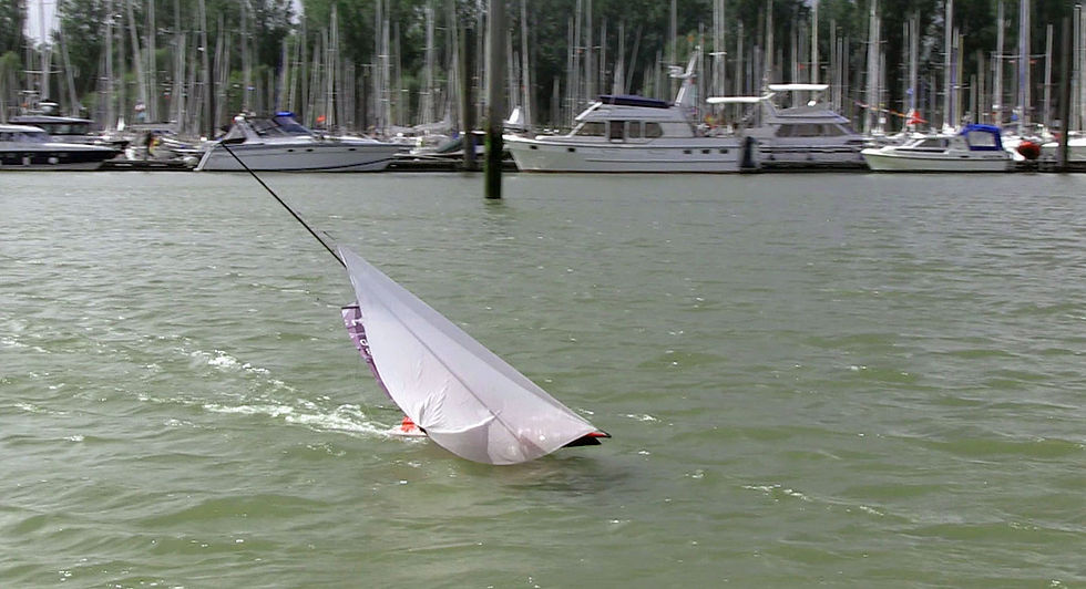
By the way, the control of the canting keel and the daggerboards are taken over from the offshore racing of real "man-carrying" yachts: The keel control system is used on some Mini 6.50. Downhaul and rehaul for the daggerboards are thus used on the VOLVO OCEAN 65. The daggerboard carbon guides above deck have been designed so that keel and both boards can be controlled by one winch.
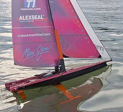
All of this, in combination with the gennaker, results in a breathtaking speed bulkhead, with almost no wind.
RC system: Graupner M16 with 2 long sliders in the middle
top right, proportional without spring return: Furler (gennaker roller)
right stick up/down with detent: canting keel
right stick left/right with spring return: Rudder
left stick up/down with detent sail adjustment
left long slider: gennaker port / starboard. center: Jibe position
Very important: If the gennaker sheet slider on the remote control is in the middle, then the sheet must be just long enough to allow the gennaker to be completely rolled up. Not longer, because otherwise the sheet can get caught too fast. It blows too far out, and can hook behind the main boom, for example.
Adjust the gennaker with the slider, and follow the gennaker, and keep the boat in the right balance with the jib/major on the left stick, when the keel is already at the stop. And can pump in the wave via jib/major in the shaft.
Dimensions
Length:1550 mm
Total height in the stand: 2570 mm
Length waterline: 1430 mm
width: 306 mm
Draught: 480 mm
Mast height above deck: 2040 mm
total weight: 5,2kg
Material Deck/Hull: Carbon
Material mast: Carbon
The Rigg
The mast seemed a little too soft, but the prototype is simply too heavy to be optimized further. Personally, I like ships that harmonize well as a complete system. This is probably because I have been sailing FD since 1984. In the Flying Dutchman you have the possibility to adjust all trim aspects during the trip. You are fast if you can adjust the system for different wind conditions and wave heights. You get really fast if you don't have to move so much around the boat, but the mast does part of the trim, namely the fine trim, by itself.
Over many years we have tested very intensively and have come to the conclusion that high shroud tension - to get a very straight genoa luff flat - quickly leads to the mast bending (collapsing) little or uncontrollably. A mast that is too hard means that the helmsman (in this case me) has to correct every wind change manually. With a soft mast the mainsail changes over the whole surface, becomes flatter and twists more. This means that the profile is automatically optimized for a higher wind speed - without any action from the helmsman, who can then concentrate more on tactics. This, once recognized, has led to a radical redesign of our boat: Deck flexing away (so that the mast is not braced), short spreaders (so that it bends more to the side), and more cut-in luff slack in the genoa (to make the luff just as flat with less shroud tension -> good height upwind). This brought the desired success.

In the MegaMaxi we have the same basic geometry in the rig. No backstay, but adjustable spreaders and shroud points relatively far back. The next more difficult goal will soon be - with construction number 1 out of shape, i.e. with the correct hull weight - to adjust the rig and sails. The bigger the boat, the smaller the delta in the wind speed changes, and also the movements due to waves become proportionally smaller. In addition, the time required for tuning is as great as on a small boat, and the teams almost all have less water time/training time. This increases the risk of backfire. At 10m length it is cool, but with ASSO99, X99 and BB10 it works quite well. Since we rebuilt on the BB10 and got a new, suitable genoa, we have won almost everything. Fyn Double handed, the Elbe race to the NORDSEEWOCHE - we are not allowed to sail further because of missing sea railings :-( - and most of the Elbe regattas. And in the ASSO it is not bad either. After the Genoa fitted: First runner-up on the DM and then best German on the EURO. 1st shipping regatta. 1. Elbe finale. ...
These are the variation possibilities in the FD:

- Shrouds -> forestay tension (luff sag of the genoa/profile depth)
- Jib halyard (is also the forestay)
-> rake (masthead halyard) Sail pressure point forward/back
- genoa points up/down
-> twist of the genoa
- Genoa points inside/outside
-> angle of attack/profile depth of the genoa
- Genoa sheet -> angle of attack/depth of the genoa
- Bottom shrouds -> mast bend (mainsail profile depth and distribution)
- Cunningham -> profile depth of the mainsail
- Cunningham -> sail pressure point forward/backward & sails flatter
- Boom vang -> Twist (twist of the mainsail)
- Traveller -> luff sag of the genoa/twist of the mainsail
- Lower mainsail -> mainsail profile depth in the lower area
- Sword up/down -> lateral area and pressure point
- centreboard forward/back -> lateral pressure point forward/back
Adjustable on land only
- Salingwinkel
- Spreader length
The production
The prototype showed that the technology works: The overall balance of the ship is correct, i.e. it is neither windward nor leeward, and sailed straight ahead even when the keel and centreboard were adjusted (or was slightly windward). Unfortunately the boat has become much too heavy. The prototype hull looked quite nice, but was still quite bulky. We also used polyester filler and putty, and varnish to build it faster. The disadvantage is that the paint will sink for days. In the hundredth of a millimeter range, but you can see that against the light.
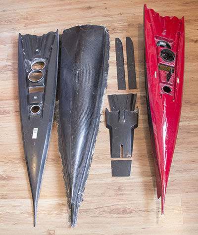
So we decided to rebuild the hull perfectly, so that we could then adjust the sails and rigging to the actual weight of the boat. We demounted all again and took a mould directly from the prototype. In that one, we sanded all the recesses cleanly and shaped them precisely, which is easier than in the positive, because they are now raised. Then we took the mould off again. So that nothing sagged, we filled everything with epoxy and colloidal silica. This is hard to sand, but nice and robust and easy to repair.
After one month the mould was finished and the parts for the first boat were laminated. The mould construction, especially for the deck mould was very complex. To grind and polish the many small surfaces and curves took forever. To make the deck fit into the hull, we glued a 1mm thick plastic strip on the edge of the first negative mould and smoothed it on. This gave us an approx. 10mm high adhesive edge which should fit exactly into the hull. The less you have to putty later, the lighter the yacht will be.
The first deck and the first hull fit well together, are stable but still too heavy. Hull and deck have been sawn off by sawing off the edges and sanding them down is certainly even easier. But we build new ones anyway. We want to build a finished hull lighter than 1.5kg. In the surfaces of the deck we reduce from 2 layers 200g carbon to one layer 200g carbon, in the curves to 2 layers 100g glass. The glass can be laminated better without air inclusions compared to carbon. With the deck we do not draw a vacuum, because the fabric layers have already slipped several times in the small details when creating the vacuum.
Test, test, test
Well, the ship worked at first good, only the person at the Rc system has to be able to operate all this. So that canting keel, gennaker and sails harmonized properly, we had to practice a bit more. Conclusion: The boat is very well balanced, daggerboards and canting keel harmonize even better than on the prototype. Then the boat was really loaded in wind and waves to see where the first thing that gets blown away was.

The basic canting keel/daggerboard function worked there as well, but a bit slowly and the uprighting moment could be higher. So we lengthened the keel again and ordered a stronger keel winch. The RMG 380EL is coming on board, which allows a smaller drum diameter with 9 revolutions and therefore has more power. The winch also has a more powerful engine than the 280 EL.
While waiting for the winch (comes from Australia) and we tested with the long fixed keel. A lot of detail work is necessary before such a ship works reliably, e.g. we replaced the metal brackets in the wetbox with carbon. This way the blocks come closer to the hull wall and the keel can be brought about 2cm higher. The new brackets are much easier to remove in case the Dyneema line for the keel control needs to be replaced and the new guides are smoother.
This makes you think about whether to steer the keel with a Giro ... how boring ... or find a system with longer, more sensitive controls. Especially the gennaker requires more feeling. More than 3 m sheet length have to be steered sensitively with the stick ... Meanwhile the prototype number 2, i.e. the first boat out of the mould, is almost finished and is being painted. Fire red metallic and black.... At least we built 5 boats, which are all sold now. A complete set wit all sails and radio was appr. 15.000,- EUR.
The weight table/weight in g/part
1500 Hull+Deck
2200 keel
360 Battery
175 Sail servo
40 Rudder servo
67 Gennaker winch
67 Furler winch
120 Keel winch
20 Recipients
30 hatches, large (3 pieces)
10 Hatch, small
150 Mast
100 sails
100 Fittings
120 2 oars (60g)
Here is one of the typical to-do lists in the test phase:
- Mount deflection blocks Rudder lines at the correct angle
- Adjust rudder exactly, too much play
- Adjust the upper edge of the rudder more precisely to the hull. Too early stalls under gennaker.
- Improve hydrodynamic design of fixed keel top edge
- Attach the water stay. Gennaker detaches in violent booms.
- Forward hatch must be flush with the deck. Gennaker sheet snagged.
- Furler line: Why is the wind blowing? Check setting of overload switch!
- Furler line should be longer - enlarge drum. If there is a lot of wind, the gennaker does not roll up fully.
- Replace the pretty polyester gennaker sheets with white ones made of smooth Dyneema. Less friction in the jibe.
- Install carbon servo arm. Bent aluminum.
- Deburr all gennaker sheets and sheet blocks
- Gennaker sheet as short as possible
- Adjust the rudder correctly, especially the upper edge to the hull. The gap must be as small as possible
- Adjust fixed keel better
- rear sheet pods do not have enough food. Reinforce deck
- Countersink the screws on the wall pedestals. The sheet remains hanging on the round-head screws
- The gennaker sheet gets caught on the carabiner on the mainsail clew. Find a solution.
- Mainsail middle wind and strong wind must be battened in the upper third
- Luff curve Jib centre wind has too much sag in the middle.
- Think of a shroud tensioner safety device
- Move the starting point for the strong wind jib downwards
- Guide eye Furler line must be closer to the drum
- Sheet block collides with rudder line. Displace the feedthrough.
- Longer rubber with 1:6 reduction for the furler line, so that the gennaker rolls out easier
- Backstay for strong wind must be positioned exactly at the strong wind gennaker attachment point
- Daggerboard circuit collides with sheet guide. Displace guide eyes
- Gennaker sheet blocks must be more strongly lined. Screws loosen
- Reinforce the groove of the carbon mast at the bottom. If you change the sails quickly, you will damage them too easily. With glass fibre 50g.
- Extend the backstay spreader
- Knot the rubbers for the gennaker sheet rotation differently, or secure the knots with superglue
- Safety line to the battery plug. It's hard to get at with thick fingers.
- Tinker cleat on screws on daggerboards to be able to tension daggerboard adjustments. Too much play.
- Canting keel winch line must be thicker. Stable enough, but too thin for the fingers/clamps, can hardly be used.
... and 100 other small things that were noticed during the process and were immediately corrected ...




Comments